Quantcast
Channel: Electronic Circuit Diagram
Viewing all 124 articles
Browse latest View live

12 Stage Water Level Indicator

$
0
0

12 Stage Water Level Indicator Circuit Diagram
The is a simple and versatile 12 stage water level indicator circuit which will show you the current water level in the tank. This circuit can be used for general purposes. This circuit generates an alarm when the water level is below the lowest level of L1 and also when the water just touching the highest level L12. The circuit is designed to display 12 different levels. However, the level display can be increased or decreased depending on the level of resolution required. This can be done by increasing or decreasing the number of levels of the metal strip detectors (L1 through L12) and related components.

In this water level indicator circuit, the diodes D1, D2 and D13 act as a half-wave rectifier. Rectified output is filtered using a capacitor C1 through C3 respectively.

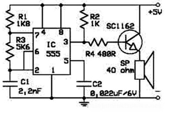
Initially, when the water level is below the L1 strip, supplying electrical oscillation frequency is not transferred to the diode D1. Thus the low output and LED1 does not light. Also, because the base voltage of the transistor T1 is low, it is in a state of cut-off and the collector voltage is high, which enables to produce melody IC1 (UM66) and the alarm is sounded.

When the water is just touching the L1 level detector strip, the oscillation frequency of the supply transferred to the diode D1. This straightening supply voltage and positive DC voltage developing capacitor C1, which is lit LED1. At the same time the base voltage of the transistor T1 becomes high, which makes forward bias and collector voltage falls to near ground potential. Disabling IC1 (UM66) and the alarm is inhibited.

Depending on the quantity of water present in the tank, which shows the level of the corresponding LED lights up. It thus showing medium level of water in the tank with a bar-chart style.

When the water in the tank just touching the highest level detector lines L12, DC voltage developed in capacitor C2. This makes it possible to produce a melody IC1 (UM66) and the alarm sounds again.

The post 12 Stage Water Level Indicator appeared first on Electronic Circuit Diagram.


LED Indicator for 220V AC Mains

$
0
0

LED Indicator for 220V AC Mains
This is the schematic diagram of LED indicator for 220V AC Mains which can be used to indicate that the cable lines is connected to 220v electrical installations.

The current through the LED is not limited to the resistor, but the capacitance of the capacitor. The capacitance can be selected so that the current passing through it could regulate directly after power LED. Since the current leads the voltage by 90°, does not arise (ideally) no power loss of the capacitor and the capacitor is not heated. Reactance capacitor can be easily calculated with the following formula:

formula

where Xc is capacitive reactance in Ohm, pi (3.14), f frequency in Hertz and C the capacitance in Farad.
A capacitor with a capacity of 100nF will have for grid frequency reactance:
1 / (2x3.14x50x10-7) = 31831 Ohm

If you connect this capacitor voltage network, it will be the power flow 230/31831 = 0.0072 A. If we connect in series with the capacitor bridge rectifier with LED, the current has substantially altered.

Resistor R1 has only one task – during off indicator light capacitor discharge and prevent unpleasant “kick” while handling the device off.

Warning: The entire circuit is connected to the high voltage electrical network. Therefore, it is necessary to work at maintaining the necessary caution.

source:http://www.belza.cz/ac-led/kontrol.htm

Incoming Search: power amplifier 2000 watt circuit diagram, Surcit dayogram, Surcit dayogram net, usb audio amplifier circuit diagram

The post LED Indicator for 220V AC Mains appeared first on Electronic Circuit Diagram.

7 Segment LED Digital Clock with IC MM5314N

$
0
0

MM5314N
This is the circuit diagram of digital clock based on IC MM5314N. The clock display uses 6 pieces of 7 Segment LED with format HH:MM:SS. The power supply for this circuit already included, so you can connect this circuit directly to the mains. The DC supply is about 5-12V.

Parts List:

R1 = 100Kohms
R2 = 47Kohms
R3 = 100Kohms
R4 ….. 10 = 2.2Kohms
R11 ….. 17 = 10Kohms
R18 ….. 24-25-26 = 220 ohmios
R25-26 = 1.2Kohms

C1 = 2200uF 25V
C2 = 100uF 25V
C3 = 18nF 100V
C4-5 = 10nF

D1 = 1N4148
Q1 a Q7 = BC550
Q8 a Q13 = BC560

IC1 = MM5314N ( Discontinue, National Semiconductor)

GR1 = 4X1N4002
T1 = 220V AC/12V 1A
DS1 a DS7 = Display Common Anodo

Datasheet document for digital clock IC MM5314N can be accessed here:
http://www.datasheetspdf.com/PDF/MM5314N/514207/1

The post 7 Segment LED Digital Clock with IC MM5314N appeared first on Electronic Circuit Diagram.

0-60V / 0-2A Variable Power Supply

$
0
0

0-60V / 0-2A Variable Power Supply Circuit Diagram

This is the circuit diagram of 0-60V / 0-2A variable power supply. Of course this circuit used to cover the voltage range from 0 to 60V and current from 0 to 2A. The maximum current can be increased, if we add the power transistors needed. Note the power output, just to cite one example, if delivery 2A 12V source to have a voltage drop of 48V with 2A consumption giving us a dissipation of 100 watts, is not a heating source, so, care.

Close attention should be paid to the way in which the two transistors BC327 circuit current protection, which work in saturation cutting work, another deals only activate an LED indicator on-load when the voltage drop lights output and will have to press the RESET button provided for the case. This will activate the output voltage again.

As already mentioned, this source has an intensity control, which disconnects the output voltage. This does not mean that supports the intersection of the (positive and negative) output cables. We must avoid this situation if possible as this will cause the destruction of transistors and other circuit components, it should be noted that we are dealing with respectable power.

For example: 5V and 2A output, this represents 65V – 5V = 60V which must be dissipated by the output transistors 2A, are talking about the power loss of 120 watts as a small “electric fire” this heat, more heat produced by 10W consumption advantage, they must evacuate 130W between the radiator and a fan that helps to lower the temperature that produces this “heater”, otherwise, you can imagine the result.

Incoming Search: sceamatic for samsung external computer speakers

The post 0-60V / 0-2A Variable Power Supply appeared first on Electronic Circuit Diagram.

5VDC Single Polarity to 12VDC Dual Polarity Converter

$
0
0

5VDC Single Polarity to 12VDC Dual Polarity Converter

This is the circuit diagram of 5VDC single polarity to 12VDC dual polarity converter based on IC LM2595-12 from National Semiconductor. This circuit will convert 5V DC single voltage (+) become 12V DC dual polarity output (+), GND, (-).

Many electronic devices need a ±12V power supply. Typical examples include analog circuits or RS-232 driver power supplies. The ±12V typically needs to be generated from a 5V system bus. The solutions normally used involve a multiple secondary transformer or multiple switching regulators. These solutions can be complicated, may require custom transformer design and may have poor efficiency and poor regulation. The 5VDC single polarity to 12VDC dual polarity converter circuit shown in above image is simple, uses only one switching regulator IC, uses a small number of components, and provides good regulation at a high efficiency. Additionally, all the components used in this circuit are off the shelf components.

The converter circuit in above image uses an LM2595-12 (buck SIMPLE SWITCHER™) based switching regulator to generate both the +12V and the -12V outputs from 5V input. The LM2595 is configured as an inverting buck-boost converter to obtain the negative output. The positive output is generated using an additional winding in the off-the-self inductor (CTX250-4 from Coiltronics) used in this circuit. Only one additional diode (D3) and a capacitor (C3) are needed to generate the positive output.

This circuit come from Application Note #1118 by National Semiconductor about Simple Regulator Provides ±12V from 5V Source using LM2595-12.
Download the application note AN-1118:

The post 5VDC Single Polarity to 12VDC Dual Polarity Converter appeared first on Electronic Circuit Diagram.

70W OCL Power Amplifier

$
0
0

70W OCL Power Amplifier Circuit

This is the circuit diagram of 70W OCL power amplifier with output power of 70 watts single channel. It uses power transistor TIP2955 and TIP3055 as main component. The power supply used for this amplifier is a symmetrical / dual polarity power supply with output voltage 25V – 32V. This amplifier dan be used to drive the 4-16 Ohms loudspeaker. For stereo sound system application, you need to make two similar circuit and use 5A transformer for power supply.

What is OCL Amplifier?

An OCL amplifier (output capacitor-less amplifier) is any audio amplifier with direct-coupled capacitorless output. Typically, OCL amplifiers can be any of several amplifier classes, and typically have a push-pull output stage (wikipedia).

Advantages of OCL amplifiers over capacitor-coupled amplifiers include:

  1. Avoiding the cost and bulk of an output capacitor
  2. better immunity to motorboat oscillation
  3. larger output power at very low frequencies and DC

I wish you luck with this 70W OCL power amplifier project. :)

The post 70W OCL Power Amplifier appeared first on Electronic Circuit Diagram.

12W Audio Amplifier based MOSFET 2SK135 / 2SJ50

$
0
0

12W Audio Amplifier based FET Scheme

This is a small 12W audio amplifier over a load of 8 Ω, that combining the NE5534 integrated with a pair of V-MOSFET transistor output stage technology as we get excellent sound performance. MOSFET 2SK135 / 2SJ50 from Hitachi is used in this circuit. Input sensitivity of the circuit is 3V RMS maximum, the distortion factor is 0.002% at 1 kHz, and the frequency response is 15 Hz to 100 kHz. (-3dB).

This circuit requires a symmetrical (dual polarity) power supply with voltage output +/- 25V and the current output should be 2A maximum.

12W Audio Amplifier Components List:

R1 = 33 kΩ C1 = 1nF 63V D1 = 1N967B zener 18V 0.5W
R2 = 6.8 kΩ C2 = 47 µF 40V D2 = 1N967B zener 18V 0.5W
R3 = 22 kΩ C3 = 100 nF 63V D3 = 1N4148
R4 = 100 kΩ C4 = 100 nF 63V D4 = 1N4148
R5 = 1 kΩ C5 = 47 µF 40V Q1 = 2SK135 MOSFET
R6 = 330 Ω C6 = 4.7 pF ceramic Q2 = 2SJ50 MOSFET
R7 = 1 kΩ C7 = 100 µF 40V IC1 = NE5534
R8 = 10 kΩ C8 = 100 µF 40V
R9 = 0.47 Ω 2W
R10 = 0.47 Ω 2W
R11 = 10 kΩ

Power Supply Specification:
Voltage: Symmetrical 25V
Current : 1A – 2A Max

MOSFET 2SK135 and 2SJ50 Datasheet Downloads:


The post 12W Audio Amplifier based MOSFET 2SK135 / 2SJ50 appeared first on Electronic Circuit Diagram.

Home Telephone Call Recorder

$
0
0

Home Telephone Call Recorder Wiring Diagram

This is the circuit connection of home telephone call recorder that uses very few components. In order to understand its working, we must first have the basic knowledge of standard telephone wiring and a stereo plug. In some countries, landline telephones primarily use RJ11 wiring, which has two wires—tip and ring. While tip is the positive wire, ring is the negative one. And together they complete the telephone circuit. In a telephone line, voltage between tip and ring is around 48V DC when handset is on the cradle (idle line). In order to ring the phone for an incoming call, a 20Hz AC current of around 90V is superimposed over the DC voltage already present in the idle line.

The negative wire from the phone line goes to IN1, while the positive wire goes to IN2. Further, the negative wire from OUT1 and the positive wire from OUT2 are connected to the phone. All the resistors used are 0.25W carbon film resistors and all the capacitors used are rated for 250V or more. The negative terminal of “To AUX IN” is connected to pin 1 of the stereo jack while the positive terminal is connected to pins 2 and 3 of the stereo jack. This stereo jack, in turn, is connected to the AUX IN / Audio Input of any recording device, such as computer, audio cassette player, CD player, DVD player, etc. In this case, we will use a computer desktop / notebook to make a call record.

When a call comes in, around 90V AC current at 20Hz is superimposed over the DC voltage already present in the idle line. This current is converted into DC by the diodes and fed to resistor R1, which reduces its magnitude and feeds it to LED1. The current is further reduced in magnitude by the resistor R2 and fed to the right and left channels of the stereo jack, which are connected to the AUX IN / Audio In port of a computer, in most of notebook devices, it is same between Audio Input / Mic Input.

Any audio recording software can be used to record the home telephone call, i.e AVS Audio Editor, Audacity Audio Recorder, or Audio Recorder for Free. When a call comes in, one needs to launch the audio recording software and start recording.

For phone recording, simply connect the stereo jack to the “audio input” or “mic input” port of the PC/Notebook. Install the audio recorder software on your PC/Notebook. Run the software and check the setting to ensure that the input is correct. Now you are ready to record any call. As soon as a call comes in, press the record button on the software and then pick up the telephone receiver and answer the call. Press the stop button once the call ends and then save the file in a desired location. Each software may has different setting, you can read the manual of each software about how to record an audio.

You may change the value of resistor R2 if you want to change the output volume. You can use a variable resistor in series with R2 to vary the volume of the output the home telephone call recorder circuit. The recorded audio clip can be edited using different options in the Audio Recorder software.

You can built the circuit on a general-purpose PCB and enclose it in a small box. Use an RJ11 connector and stereo jack for connecting the telephone set and computer desktop/laptop (for call recording). Telephone cords can be used to connect to the phone line and the home telephone call recorder circuit. Use of a shielded cable is recommended to reduce disturbances in the recording so it we will get good audio performance from the recording. These disturbances can also be reduced by increasing the value of R2 to about 15K.

This circuit was tested, come from EFY mag, Dec 2009. Download the PDF version:

The post Home Telephone Call Recorder appeared first on Electronic Circuit Diagram.


3V Strobe Light Miniature

$
0
0

3V Strobe Light Miniature Circuit Diagram

This is the circuit diagram of 3V strobe light miniature. The strobe lights are generally used to create nice looking visual effects in disco halls and auditoria. This post explain how to build the circuit of a battery operated portable miniature strobe light, using inexpensive components.

For convenience and simplicity, an ordinary neon lamp is used here in place of the conventional Xenon tube. The whole gadget can thus be easily mounted in a small cabinet, such as a mains adaptor cover, with a suitable reflector for neon lamp to give a proper look. Because of the electric current need of this circuit is very small, it may be powered by two medium-size dry cells (3V) or Ni-Cd cells (2.4V).

Transistors T1 and T2 in the circuit form a complimentary-pair amplifier. When switch S1 is momentarily depressed, the circuit oscillates because of the positive feedback provided via resistor R2 and capacitor C1 to the base of transistor T1. The sharp pulses in the secondary windings induce a high voltage in primary windings of transformer X1, which in fact is a line driver transformer (used in reverse) generally used in 36cm TV sets.

High voltage pulses induced in primary side are rectified by diode D1 and rapidly charge reservoir capacitor C2 to nearly 300V DC. When switch S1 is released, capacitor C2 holds the voltage level for a finite period while capacitor C3 charges slowly through resistor R3. When voltage across capacitor C3 becomes high enough, neon strikes and the capacitor rapidly discharges through the lamp. When voltage across capacitor C3 falls below the extinguishing potential of neon lamp, it goes off and capacitor C3 starts charging again. This cycle keeps on repeating for a short time, based on the reservoir capacitor C2’s value.

Warning: The neon lamp flasher section of this 3V strobe light miniature circuit carries dangerously high voltages. All precautions should therefore be taken for protection. Before any repair work, discharge capacitor C2 using a short length of wire with a 100k resistor connected in series. Use this circuit with your own risk.

The post 3V Strobe Light Miniature appeared first on Electronic Circuit Diagram.

Simple and Low Cost Dew Sensor

$
0
0

Simple and Low Cost Dew Sensor

This is a simple and low cost dew sensor circuit that can be used to switch off any gadget automatically in case of excessive humidity. Dew (condensed moisture) adversely affects the normal performance of sensitive electronic devices.

The main part of this circuit is a low cost dew sensor element (resistor type). Although dew sensor elements are widely used in video cassette players and recorders, these may not be easily available in local market. However, the same can be procured from authorised service centres of reputed companies. The author used the dew sensor for FUNAI VCP model No. V.I.P. 3000A (Part No:6808-08-04, reference no. 336) in his prototype. In practice, it is observed that all dew sensors available for video application possess the same electrical characteristics irrespective of their physical shape/size, and hence are interchangeable and can be used in this project.

This simple and low cost dew sensor circuit is basically a switching type circuit made with the help of a popular dual op-amp IC LM358N which is configured here as a comparator. (Note that only one half of the IC is used here.) Under normal conditions, resistance of the dew sensor is low (1 Kohm or so) and thus the voltage at its non-inverting terminal (pin 3) is low compared to that at its inverting input (pin 2) terminal. The corresponding output of the comparator (at pin 1) is accordingly low and thus nothing happens in the circuit.

When humidity exceeds 80%, the sensor resistance increases rapidly. As a result, the non-inverting pin becomes more positive than the inverting pin. This will push up the output of IC1 to a high level. As a consequence, the LED inside the optocoupler is energised. At the same time LED1 provides a visual indication. The optocoupler can be used to any electronic device for switching purpose.

This circuit uses a low voltage, low current power supply unit. The diode D1, resistors R8 and R6 and capacitor C1 do the job. This simple power supply module obviates the requirement for a bulky and expensive step down transformer.

The post Simple and Low Cost Dew Sensor appeared first on Electronic Circuit Diagram.

Bicycle Directional Lights

$
0
0

Bicycle Directional Lights Indicator Circuit

This is the electronic bicycle directional lights circuit that use inexpensive components and is a good substitute to many commercially available versions in the marketplace. This circuit works in an extremely different manner and is convenient to operate.

The bicycle direction indicators circuit works off a 9V PP3 (alkaline-type) battery and is basically a set of two independent free-running oscillators (astable multivibrators) built around four low-power transistors and a few passive components. Both the square-wave oscillators (one built around T1 and T2 and the other built around T3 and T4) drive four red LEDs (LED1 and LED2, and LED5 and LED6, respectively), which blink to indicate the direction of turn. Additional steady-glow LEDs (LED3 and LED4) are incorporated to indicate the working status.

How the Bicycle Directional Signal Lights Works

When switch S1 is flipped to “on” position, DC supply from the battery is extended to the oscillator circuit formed by transistors T1 and T2. Now the left-side oscillator starts oscillating and the visual indicators at the front left (FL) and rear left (RL) start blinking at a rate determined by timing capacitors C1 and C2. Resistors R2 and R3 limit the operating current of LEDs (LED1 and LED2). At the same time, the green LED (LED3) starts glowing to indicate the present direction status.

Similar action happens in the next oscillator circuit built around transistors T3 and T4 when switch S2 is flipped to “on” position. Indicators at the front right (FR) and rear right (RR) start blinking, and at the same time the green LED (LED4) glows to indicate the direction status.

Switch S3 is used for emergency indication. When it is flipped to “on” position, both the oscillators get power supply through diodes D1 and D2. As a result, LED1 through LED6 start working simultaneously. In this condition, all the LEDs blink, except LED3 and LED4, which glow steadily.

Bicycle Directional Lights Assembly

After assembling the circuit on a general purpose PCB, enclose it in a suitable cabinet as shown the following image and mount on the handle bar of the bicycle, preferably at the mechanical centre point.

Bicycle Directional Signal Lights

Connect switch S1 at the left-hand side, S2 at the right-hand side and emergency switch S3 in the middle of the master unit. Now place this master unit at the top of the handle bar and do the essential interconnections using flexible wires. Connect the front indicators (LED1 and LED5) to the left and right side of the handle and similarly rear indicators (LED2 and LED6) can be mounted in the carrier frame of the bicycle.

Bicycle Direction Indicators

For the direction indicator, you can use the direction symbol and place it at the centre of the handle, look at above image for reference.

The post Bicycle Directional Lights appeared first on Electronic Circuit Diagram.

Glow Plug Control Module

$
0
0

Glow Plug Control Unit Schematic

This is the glow plug control module unit to raise the air temperature inside the engine cylinder for quick and reliable starting, to extend the battery life and reduce the diesel consumption. In diesel engines, the air in the cylinders is not hot enough to ignite the fuel under cold conditions. Therefore every cylinder of these engines is fitted with an electric heater known as “glow plug”. A control module circuit is important to optimise the functioning of glow plugs.

How the Glow Plug Control Module Works

It utilizes a simple timer circuit built around MOSFET T1 for reliability and simplicity. Momentary pushing of switch S2 charges capacitor C1 rapidly via resistor R1. When the voltage on capacitor C1 exceeds the threshold voltage of the gate (G) of MOSFET T1, it starts charging reservoir capacitor C2 and simultaneously energises relay RL1. MOSFET T1 remains conducting as long as the voltage on C1 is greater than the threshold voltage of the MOSFET gate.

Glow Plug Controller Pin Configuration BS170 BC548

The “on” time period depends on the value of capacitor C1 and resistor R2, which govern the discharge current of capacitor C2. The component values given here will produce “on” time of around 25 seconds. In effect, when you press switch S2 momentarily, the relay energises for about 25 seconds and the glow plug gets the power supply through its contact.

The red LED (LED1) indicates that the heating process of glow plugs is “on”. When the “on” time is over, the green LED (LED2) turns on for a while, followed by a short beep from the buzzer, which indicates that the engine is ready for starting. Glow plugs draw a heavy current, hence high-current-rating contacts of an automotive relay are needed.

Build the glow plug control module unit on any general purpose PCB and mount it in a suitable case/box. Connect the glow plug wire to the relay contact. The 12V battery source that already available with the vehicle can be used to power the circuit. Connect the piezobuzzer and LED1 and LED2 through an external connection and place it at a convenient location for the driver to work.

The post Glow Plug Control Module appeared first on Electronic Circuit Diagram.

Protector for Electronic Appliance with Three-Phase Power

$
0
0

Protector for Electronic Appliance with Three-Phase Power

This is the circuit design of the protector for electronic appliance with three-phase power supply. Many of electronic appliances need three-phase AC supply to work. If there is any failure of any of the phases, then it will make the appliance prone to erratic functioning and may even lead to failure. Hence it is of paramount importance to monitor the availability of the three-phase supply and switch off the electronic appliance if found any failure on one or two phases. The power to the appliance should resume with the availability of all phases of the supply with certain time delay in order to avoid surges and momentary fluctuations.

The electronic appliance protector needs three-phase AC power, three 12V relays and a timer IC NE555 along with 230V coil contactor having four poles to switch on and switch off the appliance.

How the protector circuit works

Relays RL1 and RL2 act as a sensing devices for phases Y (Yellow) and B (Blue), respectively. These relays are connected such that each acts as an enabling device for the subsequent relay. Therefore the combination of the relays forms a logical AND gate connected serially.

The availability of phase R (Red) energises relay RL1 and its normally opened (N/O) contacts close to connect phase Y to the input of transformer X2. The availability of phase Y energises relay RL2 and its N/O contacts close to connect phase B to the input of transformer X3, thus applying a triggering input to timer IC NE555 (IC1).

Therefore the delay timer built around NE555 triggers only when all the phases (R, Y and B) are available. It provides a delay of approximately four seconds, which energises relay RL3 and its N/O contact closes to connect the line to the energising coil of four-pole contactor relay RL4. Contactor RL4 closes to ensure the availability of the three-phase power supply to the appliance.

The rating of contactor RL4 can be selected according to the full-load current rating of the appliances. Here the contact current rating of the four-pole contactor is up to 32A. The availability of phases R, Y and B is monitored by appropriate LEDs connected across the secondary windings of transformers X1, X2 and X3, respectively. Hence this circuit does not require a separate indicator lamp for monitoring the availability of the three phases. When phase R is available, LED1 glows. When phase Y is available, LED2 glows. When phase B is available, LED3 glows.

The main advantage of this protector circuit is that it protects three-phase appliances from failure of any of the mounted on the backside of cabinet. Connect the appliance through external wires.

WARNING: The circuit contains mains high voltage. Make sure the AC mains is disconnected during assembly of the circuit and double check everything before connecting your circuit to the AC mains.

The post Protector for Electronic Appliance with Three-Phase Power appeared first on Electronic Circuit Diagram.

Smart Vibration Sensor Alarm

$
0
0

Vibration Sensor Alarm Circuit Design

Here the circuit design of vibration sensor alarm. Initially, when power switch S1 is flipped to “on” position, power indicator LED1 lights up immediately. IC LM555 (IC1), wired as a simple latch circuit with control input, is powered and R-C components R4 and C5 connected at its reset pin 4 force the latch to standby mode (with inactive low output). The circuit is driven into sleep mode.

As soon as vibration is detected, MOSFET T1 is fired by the positive-going pulse output from the vibration sensing mechanism built around piezo-ceramic wafer and associated components. As a result, control input pins 2 and 6 of IC1 latch are grounded. Output pin 3 of IC1 now goes high. The positive supply from output pin 3 of IC1 is extended to three-tone siren generator UM3561 (IC2) through R5, D1 and R6. Components R6 and ZD1 stabilise the input power supply of IC2 to around 3.3V. Output signals from IC2 are amplified by Darlington-pair transistors T2 and T3 to produce alert tone (police siren sound) via loudspeaker LS1.

Reset switch S1 can be used to switch off the alarm sound by resetting the latch circuit. For safety, use key-lock type switches for S1 and S2. A relay can also be connected at the output socket (SOC1) of the circuit to energise high power beacons, emergency sirens and fence electrification units.

The smart vibration sensor alarm circuit powered with a 9V DC power supply. A compact PP3-/6F22-type alkaline battery can be used to power the circuit.

The post Smart Vibration Sensor Alarm appeared first on Electronic Circuit Diagram.

DIY Electronic Cardlock Security System

$
0
0

DIY Electronic Cardlock Security System Design

Here is the DIY electronic cardlock security system that can be used as a lock to turn on dan turn off important electronic/electrical appliances. When card is inserted, depending upon the position of punched hole on the card, a particular appliance would be switched on. The card should be rectangular in shape with only one punched hole on it. Unused/broken card (ie expired credit card, student card etc) can be used for this circuit.

How The Cardlock Security System Works

The electronic cardlock security system circuit uses eight photo-transistors (T1 through T8) to sense the light. When there is no card in the lock, light from incandescent lamp L1 (40-watt, 230V) falls on all the photo- transistor detectors. Transistor T8 is used as enable detector for IC1 (74LS244). When light is incident on it, it conducts and its collector voltage goes low. This makes transistor T16 to cut-off, and its collector voltage goes high. This logic high on its collector terminal will inhibit IC1 as long as light is present on phototransistor T8.

IC1 will get enabled only when the card is completely inserted inside the lock mechanism. This arrangement ensures that only the selected appliance is switched on and prevents false operation of the system.

Cardlock System Security Design

You can make these cards using a black, opaque plastic sheet. A small rectangular notch is made on this card to indicate proper direction for insertion of the card. If an attempt is made to insert the card wrongly, it will not go completely inside the mechanism and the system will not be enabled.

When card for any appliance (say appliance 1) is completely inserted in the mechanism, the light will fall only on photo-transistor T1. So only T1 will be on and other photo-transistors will be in off state. When transistor T1 is on, its collector voltage falls, making transistor T9 to cut-off. As a result, collector voltage of transistor T9 as also pin 2 of IC1 go logic high. This causes pin 18 (output Q1) also to go high, switching LED1 on. Simultaneously, output Q1 is connected to pin 1 of IC2 (ULN2003) for driving the relay corresponding to appliance 1. Similarly, if card for appliance 2 is inserted, only output pin 16 (Q2) of IC1 will go highmaking LED2 on while at the same time energising relay for appliance 2 via ULN2003. The same is true for other cases/appliances also.

The time during which card is present inside the mechanism, the system generates musical tone. This is achieved with the help of diodes D1 through D7 which provide a wired-OR connection at their common-cathode junction. When any of the outputs of IC1 is logic high, the commoncathode junction of diodes D1 through D7 also goes logic high, enabling IC3 (UM66) to generate a musical tone.

In this electronic cardlock security system circuit IC1 (74LS244) is used as buffer with Schmitt trigger. All outputs (Q1 through Q7) of this IC are connected to IC2 (ULN2003) which is used as relay driver. IC2 consists of seven high current relay drivers having integral diodes. External free-wheeling diodes are therefore not required.

When an input of this IC is made logic high, the corresponding output will go logic low and relay connected to that pin gets energised. This switches on a specific appliance and the corresponding LED.

Once a specific card is inserted to switch on a specific relay, that relay gets latched through its second pair of contacts. Thus even when the card is removed, the specific appliance remains on. The same holds true for all other relays/appliances as well. The only way to deenergise a latched relay after removal of the corresponding card is to switch off the corresponding switch (S1 through S7) which would cut-off the supply to the desired relay.

The +5V and +12V supplies can be obtained with conventional arrangement using a step-down transformer followed by rectifier, filter and regulator (using 7805 and 7812 etc), you may find the circuit design on power supply category.

The post DIY Electronic Cardlock Security System appeared first on Electronic Circuit Diagram.


6V and 12V Car Battery Charger

$
0
0

6V and 12V Car Battery Charger Circuit Design

This 6V and 12V car battery charger circuit can be automatically charged, quickly and correctly, 6V and 12V batteries. Circuit design is divided into two series of modules that are: power supply module and the main charger module containing the regulator modules and direct current amplifier module.

How the 6V and 12V Car Battery Charger Works

A key factor in the success of the operation of the circuit is the use of good quality transformer [T1]  with very good insulation and resistance to short circuits. The Q1 through divider R1-2, of TR1 and R4, functions as a regulated current source. The current through R9 drives power transistors Q5-6, where amplified approximately x2000 times. In an unloaded car battery voltage is about 6V to 8V. With these conditions, the charge current is about 1.2A [regulated by TR1]. When the battery is charging slowly, gradually increases the voltage at its ends. 7V to enter into the D1 conducts. As the battery voltage increases, the voltage decreases at the ends of R3 Q1 made the most conductive. This continues until the current reaches about 6A. Then by means of the voltage drop across R10, is made conductive to Q4. The excess current to the base of Q5 to ground, keeping the load current constant. When the battery is fully charged [14.4V] activated in parallel to the circuit battery, consisting of R6, D8, D2 to D6. At the same time illuminates the D8 indicating that the battery has been fully charged. Simultaneously Q2 is conducting because the voltage drop on R6. The Q3 is conductive and grounded part of the stream at the base of Q5. When the voltage across the battery reaches approximately 15V current at the base of Q5 is very small, so to stop charging the battery. Diodes D5-6 protect the circuit from accidentally installing the battery or short circuits of long duration. The diode D4 protects the circuit from wrong positioning of the battery terminals. Then D9 Led lights showing connection error [ERROR]. Closing switch S2 short the diode D2 [6.8V], now we can charge 6V battery.

6V and 12V Car Battery Charger Component List

R1-11=1K ohm 0.5W 5%
R2=22K ohm 0.5W 5%
R3-5-8=10K ohm 0.5W 5%
R4=2.2K ohm 0.5W 5%
R6=100 ohm 0.5W 5%
R7=100K ohm 0.5W 5%
R9=470 ohm 0.5W 5%
R10=0.08 ohm 10W [2X0.18 ohm parallel] 5W
B1=Bridge Rectifier 25A/40V
D1-2=6.8V 0.4W Zener
D3=4.7V 0.4W Zener
D4-6-7=1N4148
D5=18V 0.4W Zener
D8=LED 5mm Yellow
D9=LED 5mm Red
Q1-2=BC557
Q3-4=BC547
Q5=BD139 [On Heatsink]
Q6=2N3055 [On Heatsink]
TR1=4.7K Trimmer Pot.
C1=4700uF 40V
C2=1uF 25V
T1=230Vac//15V 10A Transf. [See Text]
F1=Fuse 1A Slo Blo [5X20mm]
S1=2X2 Switch 10A per contact
S2=1X2 step mini switch
J1…4=Flat Pin Connector
J5=6pin Connector 2.54mm pin step
A=0-10A Ampere meter
Batt=12V or 6V Battery

6V and 12V Car Battery Charger  Adjustment

The initial charge current should be adjusted via the TR1 to 1.2A. The adjustment can be done with a 6V battery. Connect in series with the battery a current [maximum 10A]. If there is 6V battery is short-circuited through the ammeter the charger terminals and adjust the TR1 current to 1.2A. When setting the switch S2 should be in the position of 12V, i.e. open. Particular attention should be paid to the accuracy of the diodes D2 and D3 because they protect the battery from overcharging. If the differential voltage is 100mV to go to consider them as acceptable. If you encounter difficulties in the current setting and the TR1 is not enough, you can change the value of the resistor R4, to measure charge current 1.2A. The two parallel resistors constituting R10, should be placed at a distance from the printed and Q5-6, because heated. The bridge B1 and Q5-6 be mounted on heatsink having insulated electrically from this with suitable mica silicone. The bridge B1 and the board in which the circuit is mounted must be connected with short and thick cables, especially where the current is large. lines are also printed on must have the appropriate width [in the project are shown in thicker line]. The construction should be done in a nice metal box, suitable dimensions so there is good ventilation. The construction requires the expertise.

WORK WITH BATTERIES REQUIRE HIGH ATTENTION IN HANDLING BECAUSE THERE IS ALWAYS A RISK OF EXPLOSION.

The post 6V and 12V Car Battery Charger appeared first on Electronic Circuit Diagram.

Low Cost Mosquito Repellent

$
0
0

Simple Low Cost Mosquito Repellent Circuit Design

Here is the simple and low cost mosquito repellent circuit design. The circuit serves to keep the mosquitoes out of the room or the location where the device is installed. According to certain publications, the frequency emitted by the male mosquitoes is said to be around 20–25 kHz, and so within the realm of ultrasound. But according to others, it is in the region of 5–7 kHz instead; frequencies that a human ear, even an elderly one, can still hear very well. Rather than spending lots of money buying such a device, which moreover generally have a fixed frequency, we’re suggesting building one yourself , especially since the circuit proposed is very simple and cheap to build.

Mosquito Repellent Works

The low cost mosquito repellent circuit uses just a single IC, a CMOS type 4047. This very multi-purpose IC can be wired in very many operating modes, including that of the multivibrator or astable used here. The operating frequency is set by the external components C1, R1, and P1. The latter makes it possible to slightly adjust the frequency, given the uncertainty that exists over the most efective value. To best reproduce the high frequencies produced by the generator, the output transducer used is a simple tweeter, but it must be a piezo one. Such a tweeter behaves in fact much like a capacitor, and so doesn’t overload the CMOS IC outputs that are incapable of supplying a substantial current.

To obtain an output signal of sufficient amplitude while being powered from a single 9 V battery. The tweeter is connected between the 4047’s Q and Q outputs. With this condition, it possible to apply complementary (antiphase) signals to the tweeter so it ‘sees’ an alternating voltage of double the supply voltage. In purely theoretical terms, this quadruples the output power available. In practice, it’s better to regard it as tripling it, but the beneft achieved by doing it this way is nonetheless very real. All that remains is for you to place the project in the middle of the patio table or beside your lounger in order to get a taste of the calm of a summer’s evening without mosquitoes bothering you acoustically or worse, biting. At any rate, that’s what we wish for you.

Source: eeweb

The post Low Cost Mosquito Repellent appeared first on Electronic Circuit Diagram.

PWM DC Motor Controller with MOSFET

$
0
0

PWM DC Motor Controller with MOSFET Schematic

This is the simple and low cost pulse width modulation – PWM DC motor controller using a MOSFET. This kind connection for DC motor control is to prevent heat and minimize the power consumption. It controls the motor speed by driving the motor with short pulses. These pulses vary in duration to change the speed of the motor. The longer the pulses, the faster the motor turns, and vice versa.

PWM DC Motor Controller Component List

  • R1 1 Meg 1/4W Resistor
  • R2 100K Potensiometer
  • C1 0.1uF 25V Ceramic Disc Capacitor
  • C2 0.01uF 25V Ceramic Disc Capacitor
  • Q1 IRF511 MOSFET or IRF620
  • U1 4011 CMOS NAND Gate
  • S1 DPDT Switch
  • M1 Motor (See circuit notes)
  • MISC Case, Board, Heatsink, Knob For R2, Socket For U1

PWM DC Motor Controller Circuit Notes

  • R2 potensiometer to vary the speed of the oscillator and therefore the speed of M1.
  • M1 can be any DC motor that operates from 6V and does not draw more than the maximum current of Q1. The voltage can be increased by connecting the higher voltage to the switch instead of the 6V that powers the oscillator. Be sure not to exceed the power rating of Q1 if you do this.
  • Mount a heatsink on Q1 MOSFET.
  • Q1 in the parts list can handle a maximum of 5A. Use the IRF620 for 6A, if you need any higher.

The post PWM DC Motor Controller with MOSFET appeared first on Electronic Circuit Diagram.

Sine Wave to Square Wave Converter

$
0
0

Sine Wave to Square Wave Converter Circuit Design

This sine wave to square wave converter circuit is expected to provide good square waves changing a sine wave delivered from an existing generator. Its primary feature consists in the fact that no power-source is required: in this manner it can be simply connected between a sine wave generator and the device under test.

The input sine wave sustains a voltage doubler formed by C1, C2, D1 & D2 that powers the IC. IC1A amplifies the input sine wave, other inverters included in IC1 squaring the signal and delivering an output square wave of equal mark/space ratio and good rise and fall times through the entire 20Hz-20KHz range.

Sine Wave to Square Wave Converter Circuit Notes:

  • Minimum sine wave input amplitude needed for good performance: 750mV RMS.
  • Best performances are obtained with an input sine wave amplitude from 1V RMS onwards.
  • Output square wave amplitude is proportional to input amplitude.
  • Output square wave amplitude with 1V RMS input: 3V peak to peak, with R2 set at max.
  • Minimum output square wave amplitude: 2V peak to peak, with R2 set at max.
  • Substituting the two silicon diodes with germanium types (e.g. AA118, AA119), the minimum input threshold can be lowered.

This sine wave to square wave converter come from redcircuits.com

The post Sine Wave to Square Wave Converter appeared first on Electronic Circuit Diagram.

Low Cost Electronic Rat Repellent

$
0
0

Electronic Rat Repellent Circuit
After we present a circuit of electronic mosquito repellent, this time will be continued with a circuit of electronics that are not less interesting, that is electronic rat repellent circuit.

Actually the working principles of electronic mosquito repellent and mice repellent are exactly same, using echolocation disliked by both the animal. As we know, both types of animals are very distracting while in our house.

This electronic rat repellent circuit is very simple since it only uses a few different types of components. So for you who is currently studying, studying electronics, can try to practice makes this circuit because it is considered easier for beginners.

Just the information that the necessary components to built this circuit are very less, approximately less than 10 components. So it could be ascertained that the estimation of the price needed to make this series less than 5 bucks. Very suitable for beginners who want to practice making an electronic circuit.

The required components are the basic components such as resistors, capacitors, transistors, IC 555, and output in the form of the speaker. So this is the speaker who can issue echolocation with a sweep of 50 Hz. The voice is the voice of the hated rats, so mice won’t dare draw near.

You do not need to worry because these sounds will not disturb your sleep. This sound will be loud in the ears of mice, but not for the human ear.

Electronic Rat Repellent Component List

  • R1: resistor 1K8
  • R2: resistor 1K
  • R3: resistor 5K6
  • R4: resistor 480R
  • C1: capacitor 2,2nF
  • C2: capacitor 0,022uF/6V
  • IC: timer 555Q: SC1162
  • Speaker: 4 ohm

Hopefully the electronic circuits is beneficial to all readers, please share via social media.

The post Low Cost Electronic Rat Repellent appeared first on Electronic Circuit Diagram.

Viewing all 124 articles
Browse latest View live